File A121-0005The machineSR-71A systems
The Machine
Almost nothing on the SR-71 came off the shelf: not the fuel, the engines, the metal, the navigation or the suits its crews wore. It was designed to cruise at Mach 3.2 and cleared to 85,000 feet. These are its systems, as the flight manual the Air Force flew it by and the NASA reports written about it describe them.1
Data plateSR-71A, from the flight manual unless marked
- Length, with pitot mast
- 107.4 ft132.74 m
- Wing span
- 55.6 ft116.95 m
- Height to the top of the rudders
- 18.5 ft15.64 m
- Crew
- 21pilot and reconnaissance systems officer
- Loaded gross weight
- 135,000 to over 140,000 lb161 to over 63.5 t
- Fuel
- 80,280 lb of JP-7112,219 US gal in 8 tanks
- Engines
- 2 Pratt & Whitney J58134,000 lbf each in maximum afterburner (151 kN)
- Design Mach number
- 3.21maximum scheduled cruise Mach 3.17
- Altitude limit
- 85,000 ft125,908 m
- Fuel burn at cruise
- 36,000 to 38,000 lb/h2Mach 3.0 to 3.15, standard day
- Longest operational sortie
- 11.2 h2
- Titanium
- 93%2of the structural weight
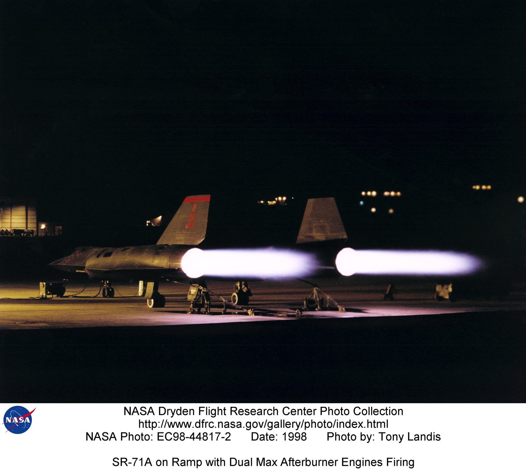
§ 1Propulsion3 exhibits
The inlet did most of the work
At cruise the J58 was not the main source of thrust. A Lockheed breakdown quoted by NASA historian Peter Merlin gives the inlet 54 percent of the thrust at Mach 3, the ejector nozzle behind the engine 29 percent and the engine itself 17 percent. At Mach 2.2 the engine still supplied 73 percent. NASA's own fact sheet puts it plainly: less than 20 percent of the thrust at Mach 3 came from the engine.2,3
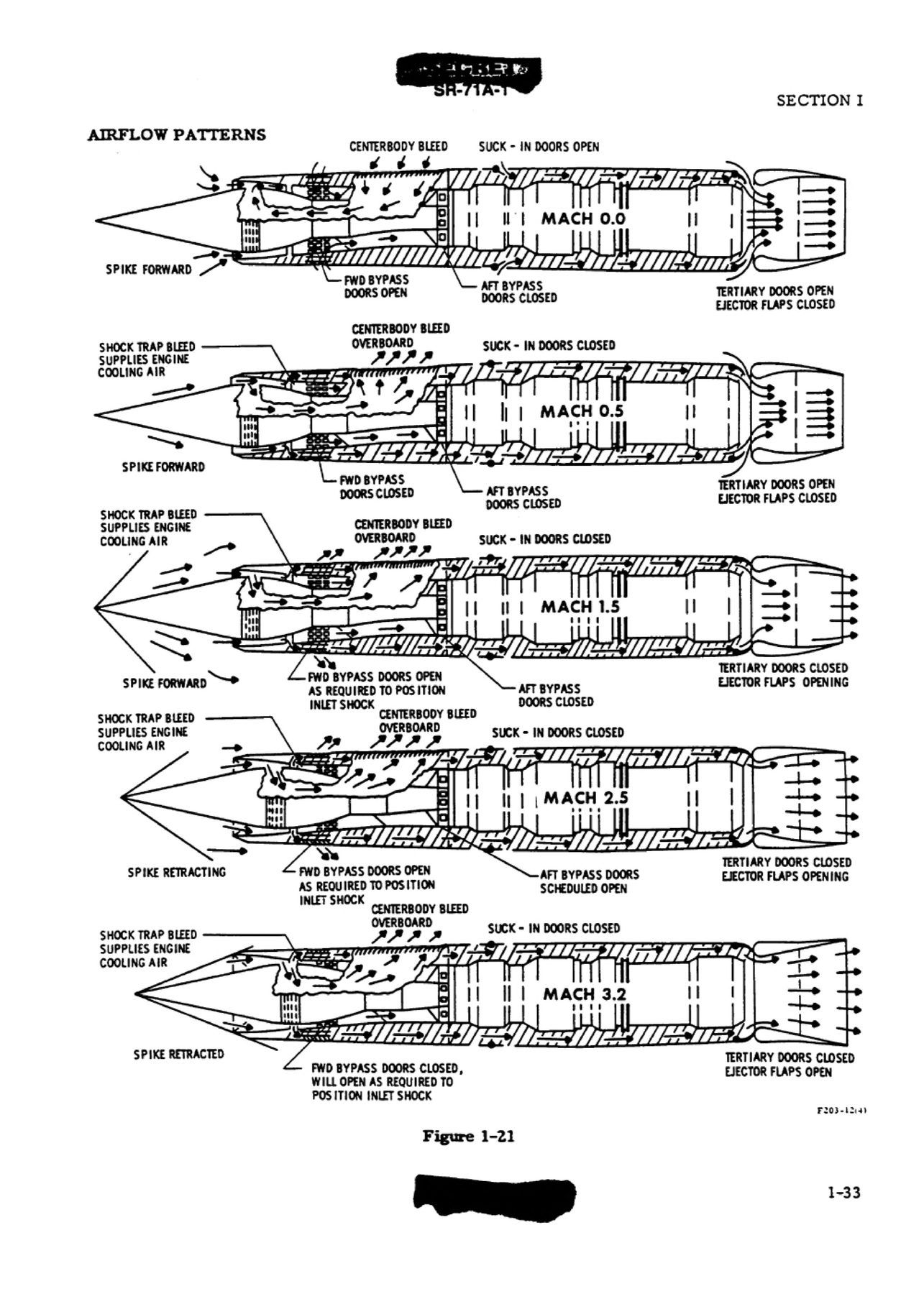
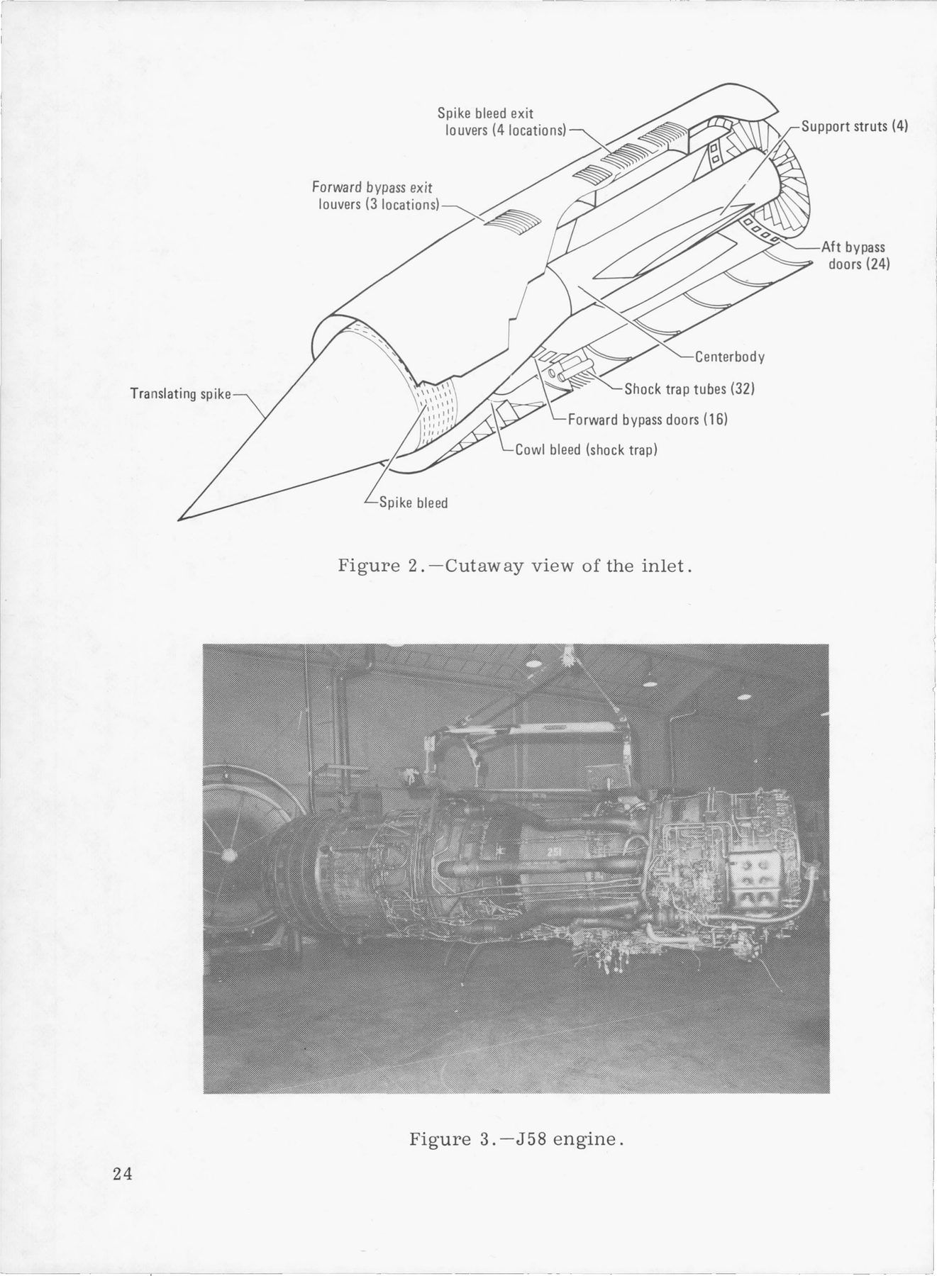
Each inlet is a mixed-compression design with a spike that moves. The spike is locked forward on the ground and below 30,000 feet. From Mach 1.6 it moves aft about 1-5/8 inches for every 0.1 Mach, to about 26 inches. As it retracts, the throat closes to 54 percent of its Mach 1.6 area while the air the inlet captures more than doubles.1
Two rings of doors keep the shock wave where it belongs. Forward bypass doors just behind the throat spill air overboard to hold the shock at the throat; aft bypass doors just ahead of the engine send air around it to the ejector. If the shock is thrown out of the inlet, an unstart, a sensor sees compressor inlet pressure fall by more than 23 percent, opens the forward bypass fully and drives the spike forward by up to 15 inches, then retracts it 3.75 seconds later.1
NASA's YF-12 flights measured how fast an unstart happens: the shock reached the spike tip in about a hundredth of a second. Between Mach 2.3 and 2.6 an unstart was violent enough to snap a pilot's head and helmet against the inside of the canopy.4,5
_(5).jpg)
Mach
Spike0.0 in aftFrom the flight manual schedule: locked forward to Mach 1.6, then about 1-5/8 in aft per 0.1 Mach, to about 26 in.
InletUnstartedThe inlet normally starts, swallowing its shock, between Mach 1.6 and 1.8.
Thrust splitPublished only for Mach 2.2 and Mach 3 cruise. Nothing in between is interpolated.
| Spike | Forward |
|---|---|
| Forward bypass | Open |
| Aft bypass | Closed |
| Centerbody bleed | Inward |
| Suck-in doors | Open |
| Tertiary doors | Open |
| Ejector flaps | Closed |
Schematic. Lengths keep the spike's travel in proportion to how far it stands ahead of the cowl lip; heights are stretched for legibility. The spike position follows the published schedule; the doors show the manual's state for the nearest Mach number it lists at or below the one chosen (0, 0.5, 1.5, 2.5 and 3.2). 1,2
§ 2Propulsion4 exhibits
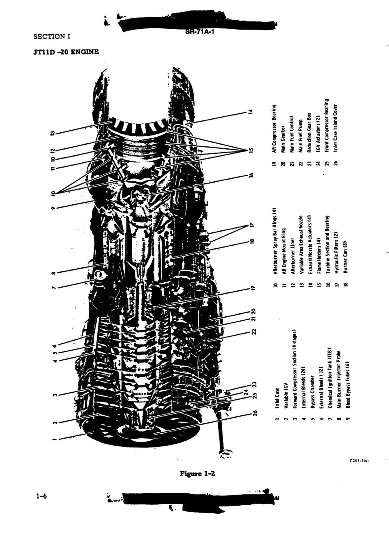
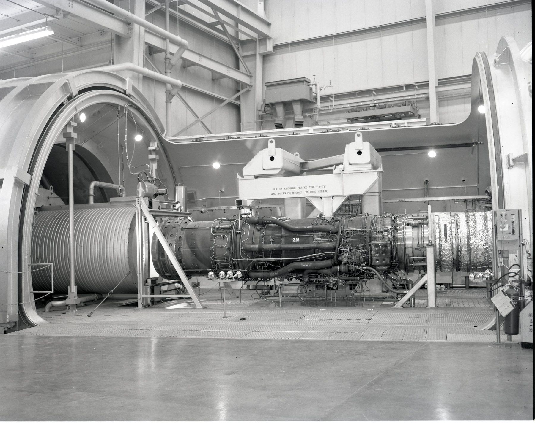
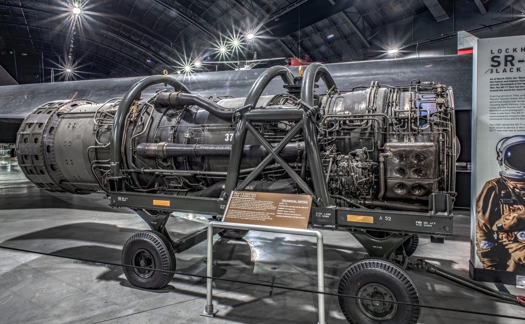
The J58, built to burn in afterburner for hours
Two Pratt & Whitney J58s, company designation JT11D-20, each rated at 34,000 lb of thrust in maximum afterburner at sea level. The 32,500 lb often quoted belongs to the early engine with fixed inlet guide vanes; the A-12's version was rated at 31,500 lb.1,5,6
Its compressor has nine stages and a pressure ratio of only 8.8 to 1, because at cruise the inlet does most of the compressing. From about Mach 1.8 to 2.0, air bled from the fourth stage flows through six tubes around the rest of the engine and straight into the afterburner.1,7
It was designed for Mach 3.2 with both full military power and afterburner run continuously, and its own fuel served as the hydraulic fluid for the nozzle, guide vanes and bleeds, at up to 1,800 psi.8,1
JP-7 is so hard to light that a lit match will not ignite it. The engines are lit chemically instead, with triethylborane, which burns on contact with air. Each engine carries enough for at least 16 shots, and a counter beside each throttle counts them down.9,1
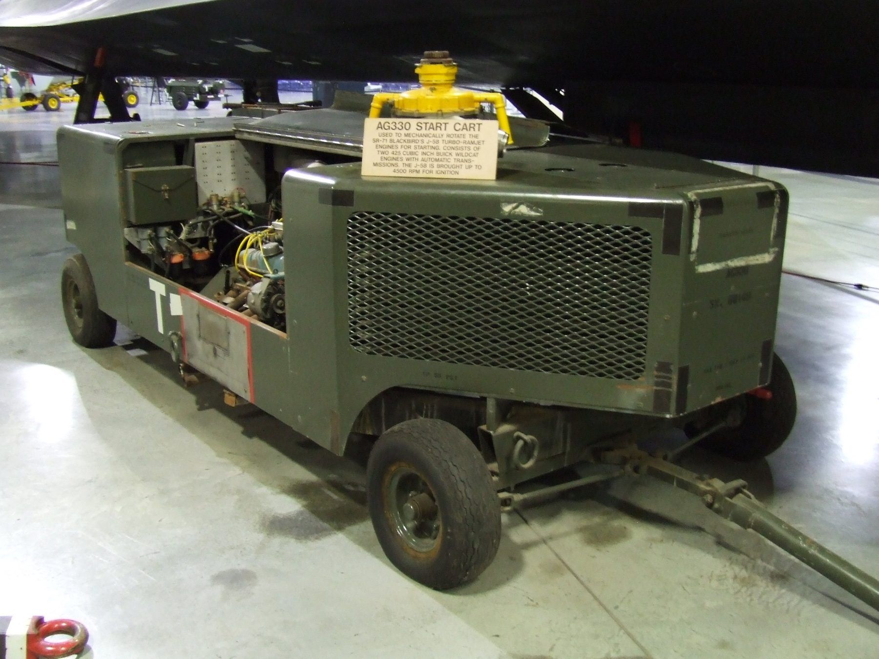
Turning a J58 over to start took more than 600 horsepower. Lockheed's answer was a cart carrying two Buick racing car engines, geared together to the engine's starter drive.8,9



§ 3Crew4 exhibits
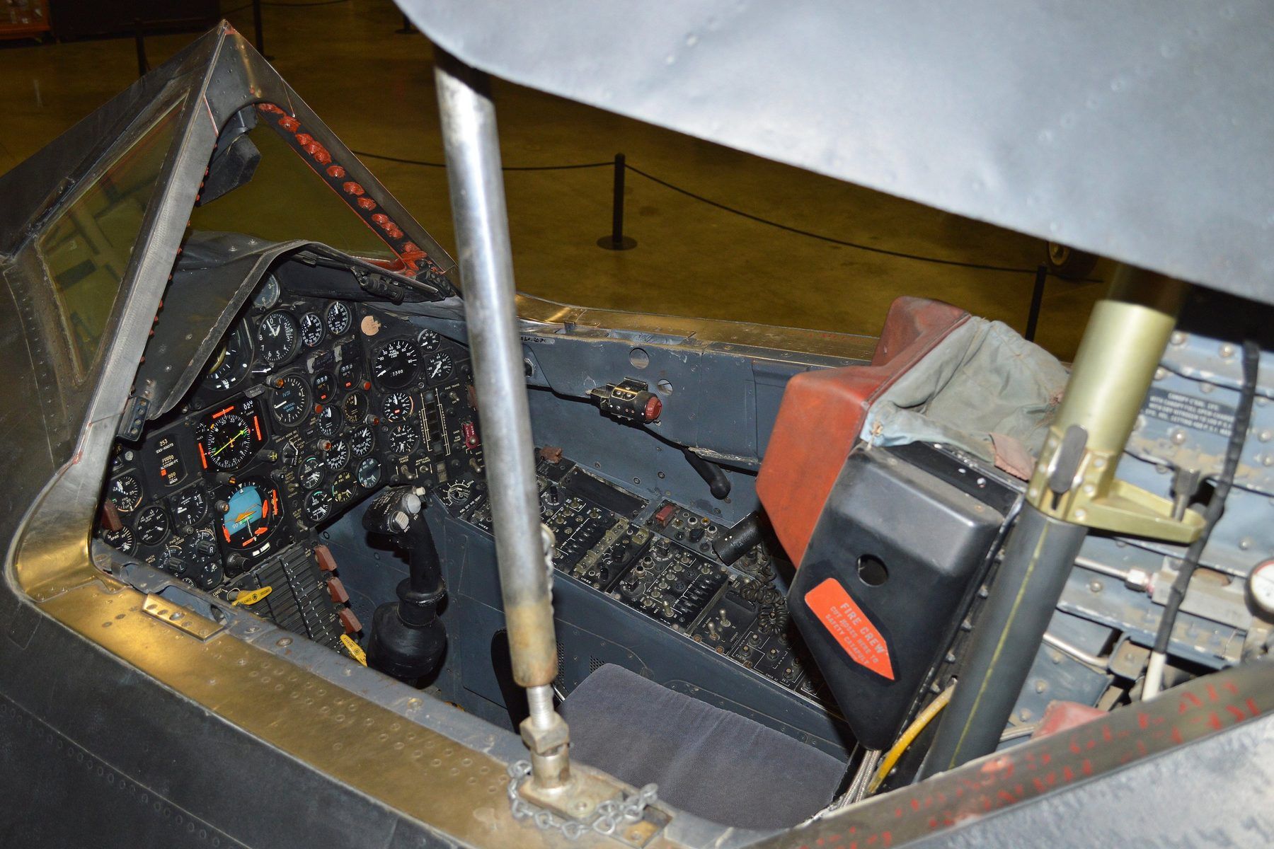
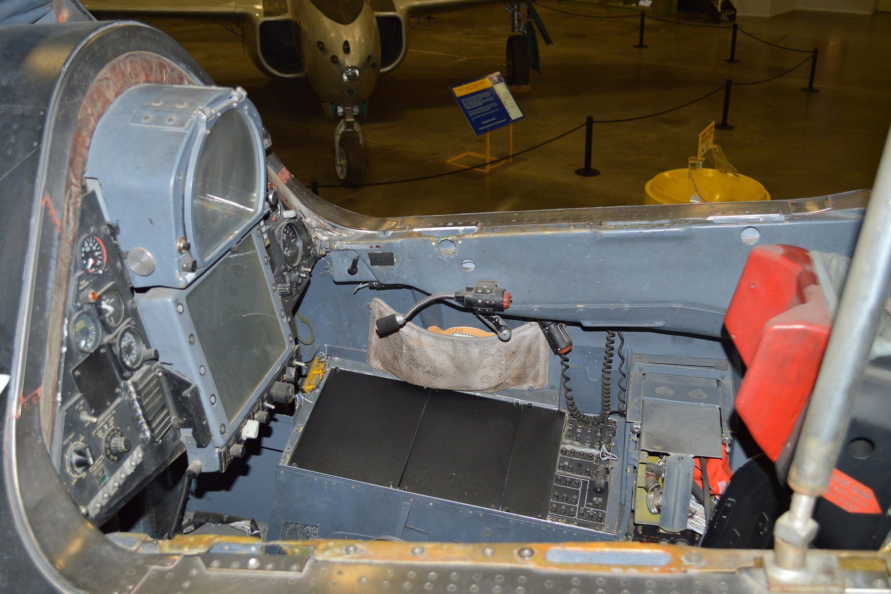
Two cockpits, and only one has a stick
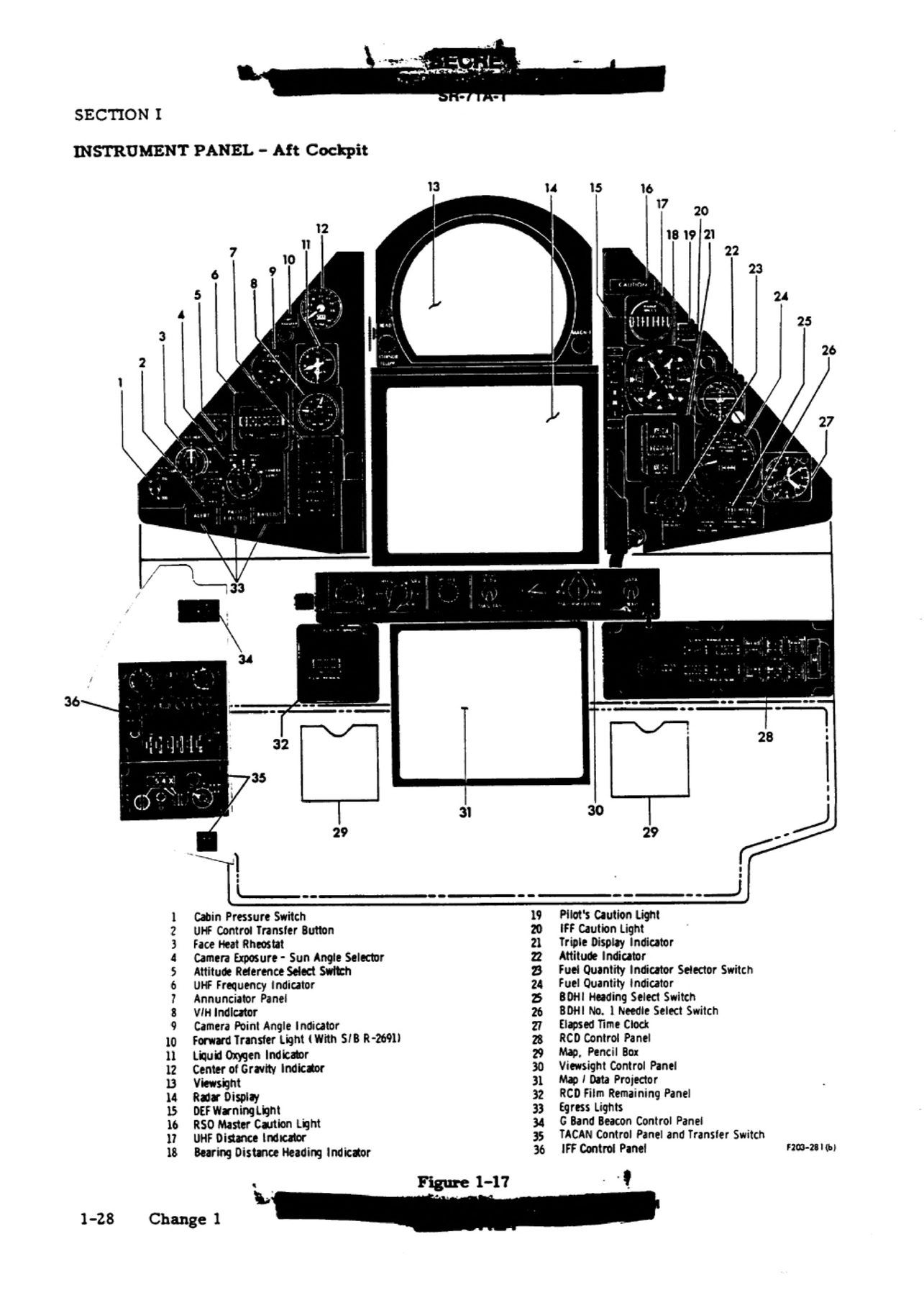
The pilot's centre panel alone has 50 numbered items in the flight manual. The attitude director indicator sits in the middle. The inlet controls are grouped at the lower left: spike and forward bypass knobs graduated in Mach from 1.4 to 3.2, and a spike position indicator reading 0 to 26 inches. The engine instruments run down the right: tachometers, exhaust gas temperature, nozzle position, fuel flow and oil pressure.1
A triple display indicator shows speed, altitude and Mach in digits. Its altitude window reads to 99,950 feet and drops the first digit above 100,000.1
Behind the pilot sits the reconnaissance systems officer, who has no flight controls: a downward-looking viewsight at the top of the panel, a radar display below it, and the sensor and navigation panels on the consoles.1
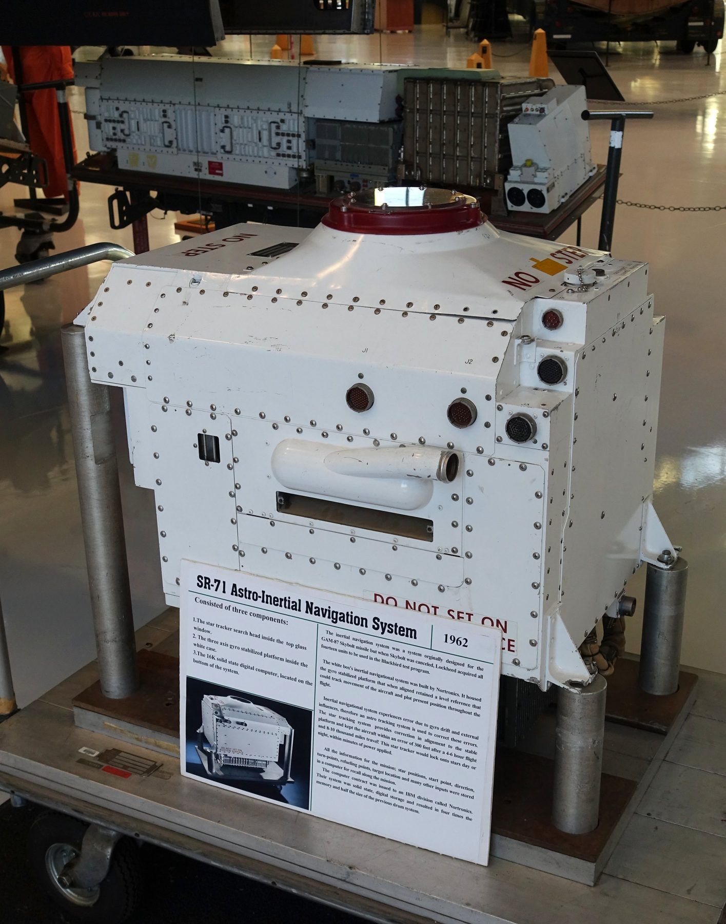
The astro-inertial navigation system steers by the stars, day and night. A telescope behind the rear cockpit looks up through a window and tracks stars from a 61-star catalogue; in astro-inertial mode the expected position error is 0.3 nautical miles for up to 10 hours.1
.jpg)
.jpg)

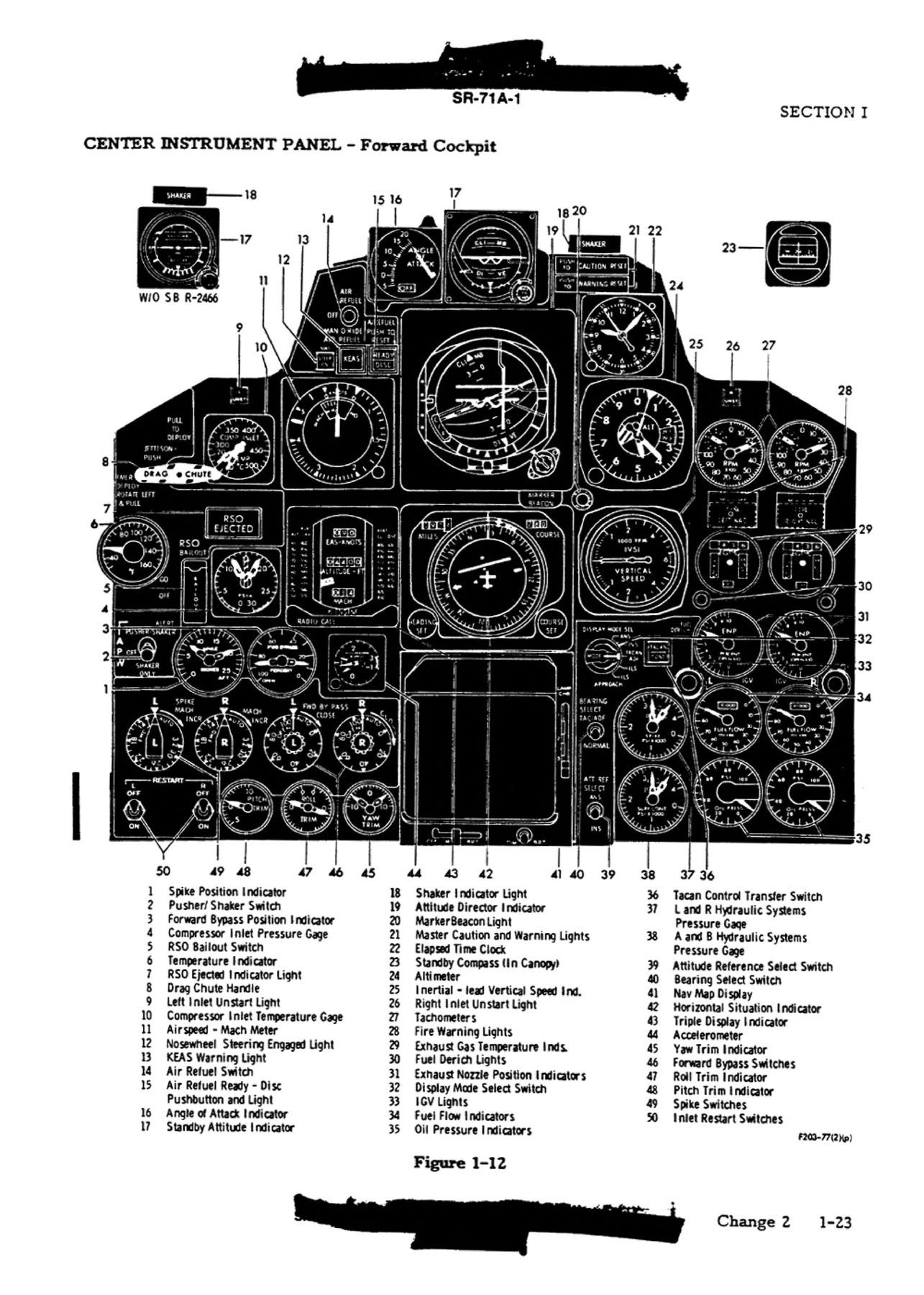
US Air Force (T.O. SR-71A-1 flight manual; Lockheed and Pratt and Whitney source artwork) · Issue E 31 Oct 1986, Change 2 31 Jul 1989 · US government work (USAF technical order); Internet Archive marks the item Public Domain Mark 1.0 · Source · Full resolution
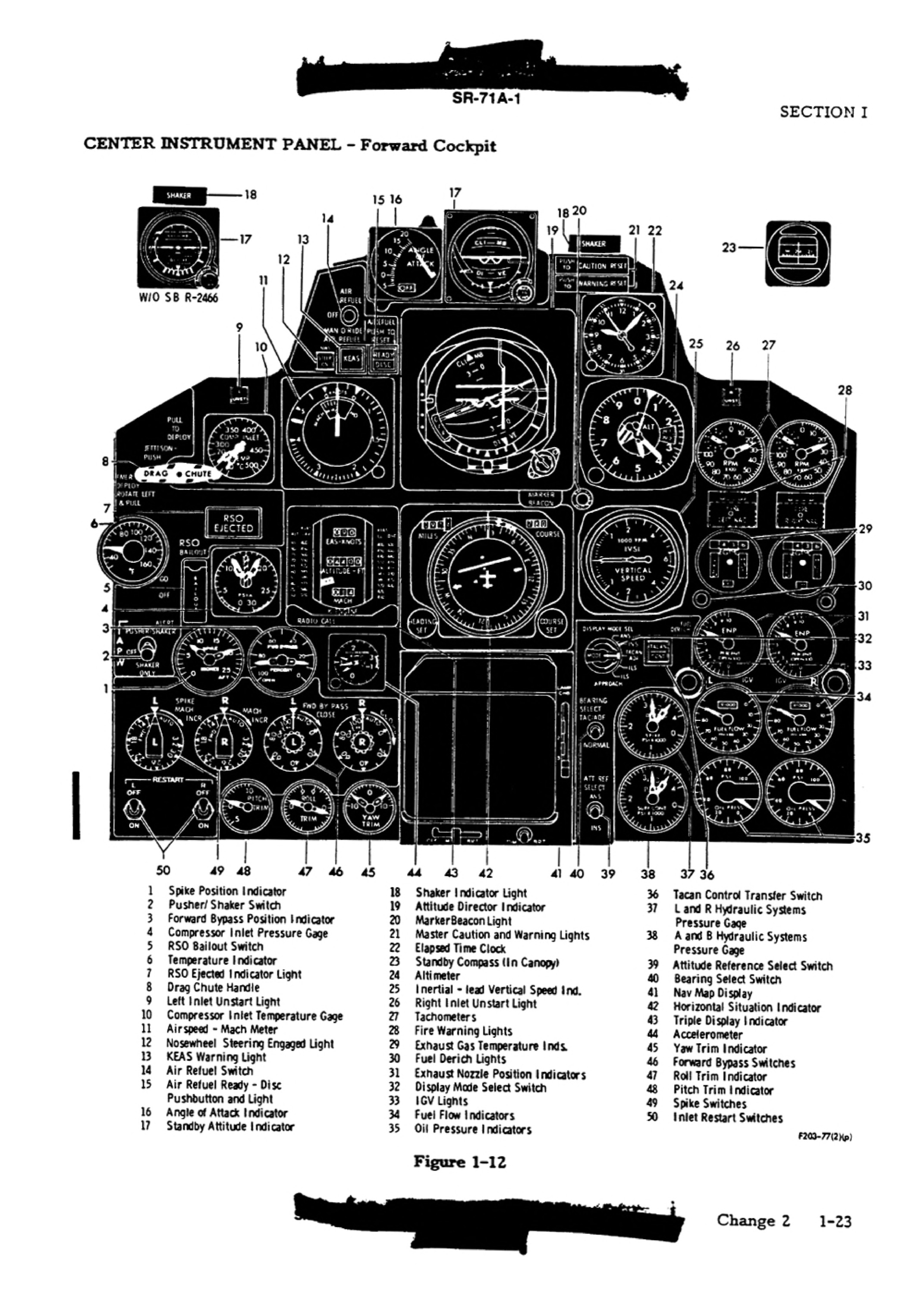
Select an instrumentTap any part of the panel, or pick from the list.
- Glareshield and top row
- Upper left
- Left column
- Inlet controls
- Trim
- Centre column
- Right of centre
- Engine column
Names and numbers from the flight manual's key to Figure 1-12. 1
§ 4Structure2 exhibits
Built to run hot
At cruise the skin averaged 462 to 622 °F and reached 1,050 °F on the nacelles. Titanium alloys make up 93 percent of the structural weight.10,2
The wing skins are corrugated chordwise so they can expand without buckling. Kelly Johnson wrote that at design heating the corrugations merely deepened by a few thousandths of an inch. The airframe as a whole grows by up to four inches in length.8,5
It is painted black to radiate heat away. In the cockpit the outer glass reached 420 °F while the cooling air came in at minus 40 °F.1,2
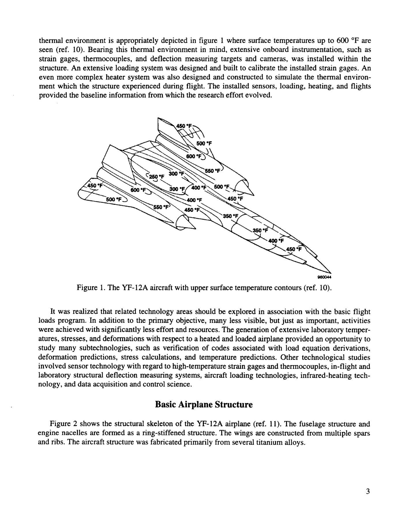
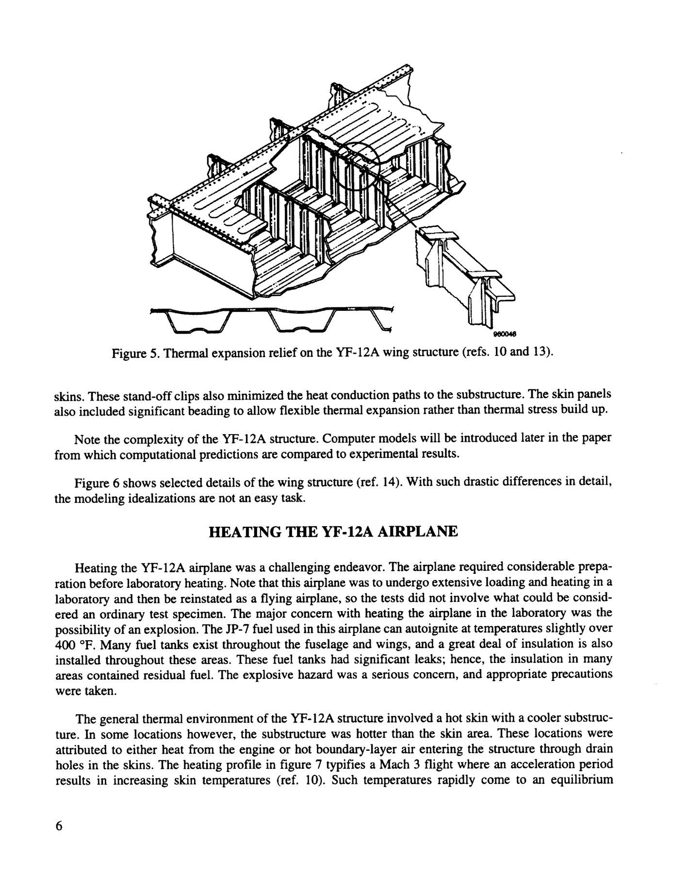
§ 5Systems2 exhibits
Fuel as coolant, nitrogen as insurance
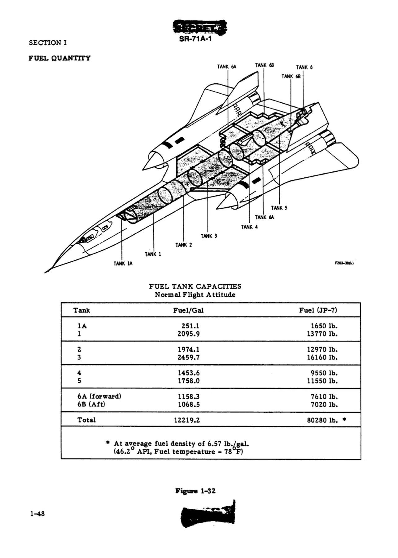
Eight tanks hold 12,219 US gallons, 80,280 lb of JP-7. Before it is burned, the fuel cools the air conditioning, the hydraulic fluid and the engine oil; once it passes 290 °F, the hottest fuel is sent back to tank 4 instead of to the engines.1
Liquid nitrogen, 262 liters in three flasks, pressurises the tanks and fills the space above the hot fuel so it cannot ignite. Without it the aircraft is limited to Mach 2.6.1
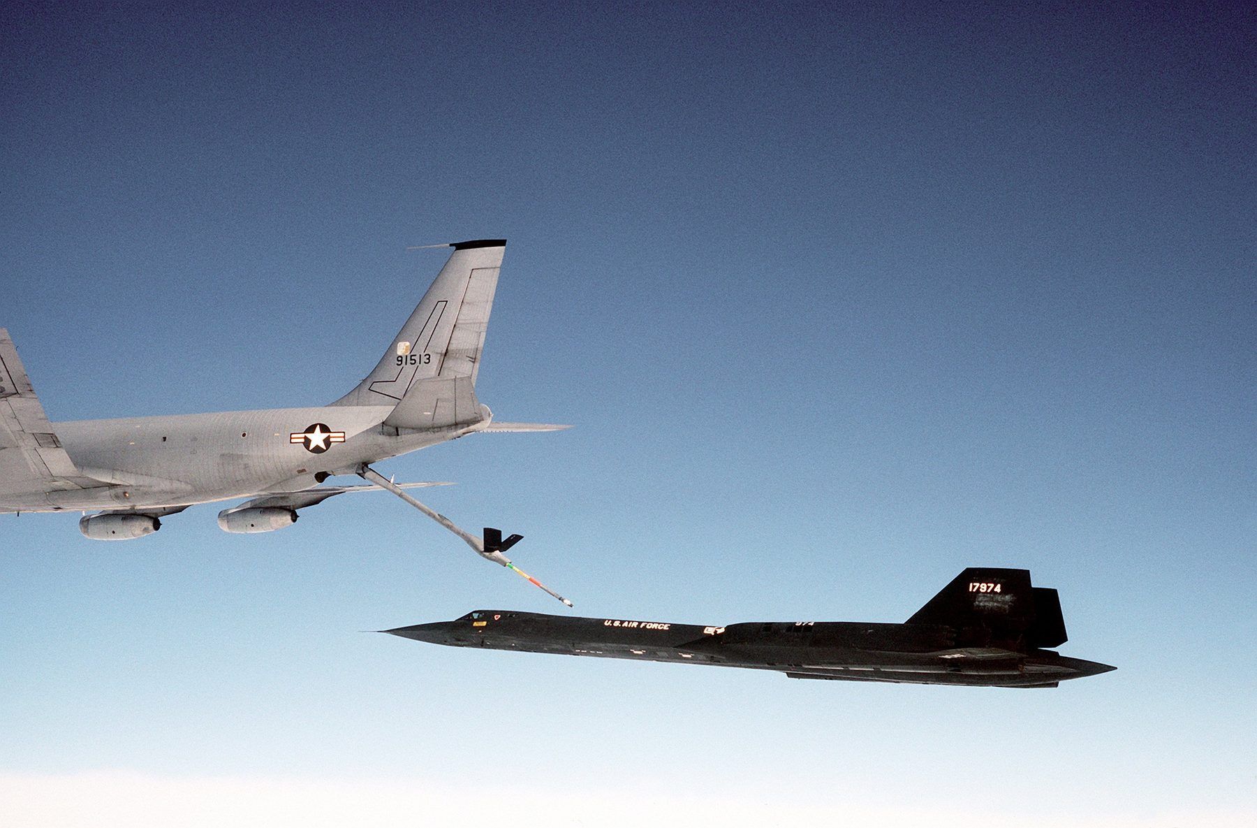
In the air it took on fuel at about 6,000 lb a minute, every tank filling at once in 12 to 15 minutes, from a dedicated fleet of KC-135Q tankers.1,11

§ 6Crew2 exhibits
Getting out at Mach 3
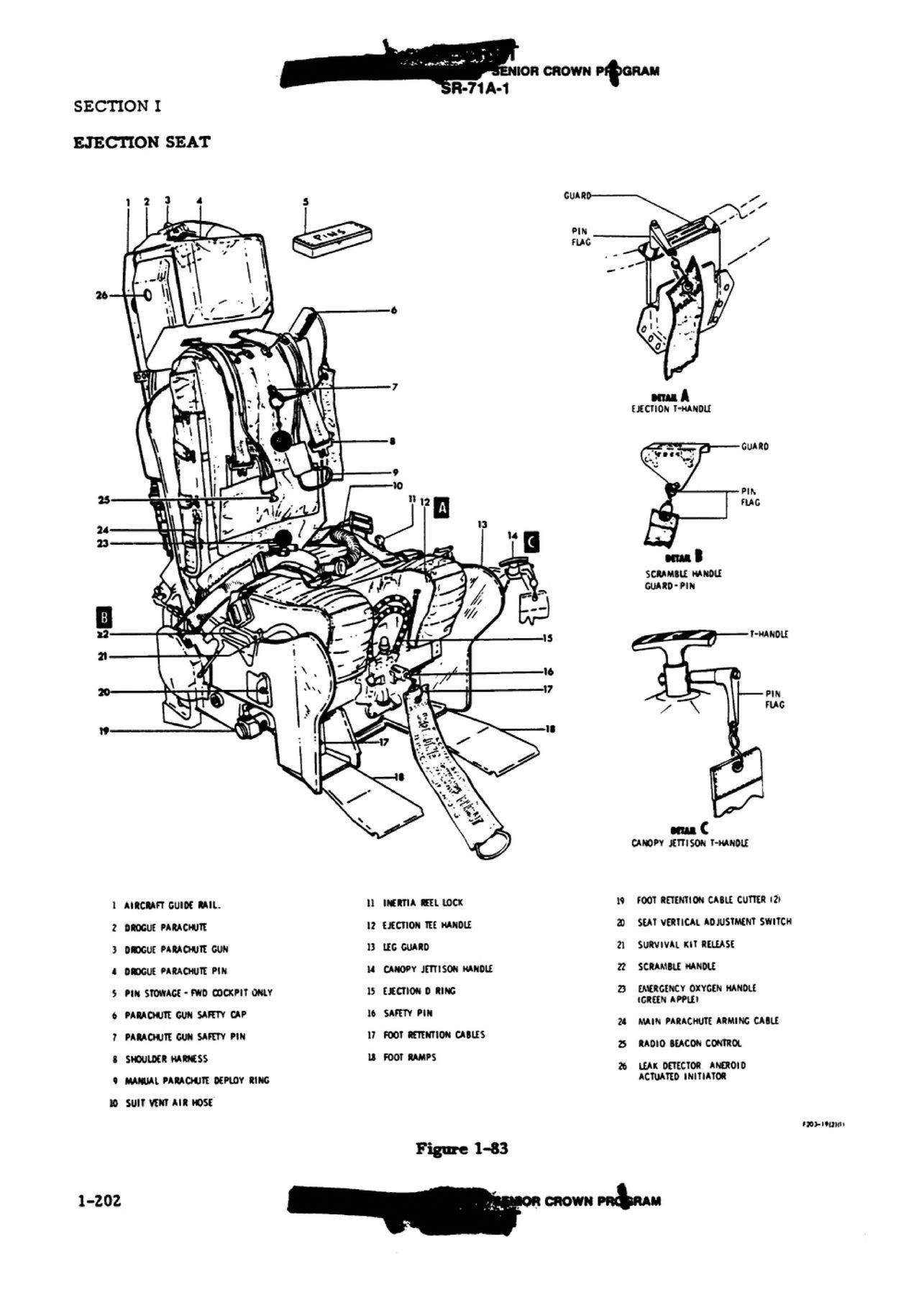
Both crew sat on Lockheed SR-1 rocket ejection seats, usable from zero speed and altitude to the edge of the flight envelope. Pulling the D-ring jettisons the canopy and then fires the catapult; the rocket lights as the seat clears the sills, a drogue opens from the headrest, and at 15,000 feet the seat throws its occupant clear before a 35-foot parachute opens.1
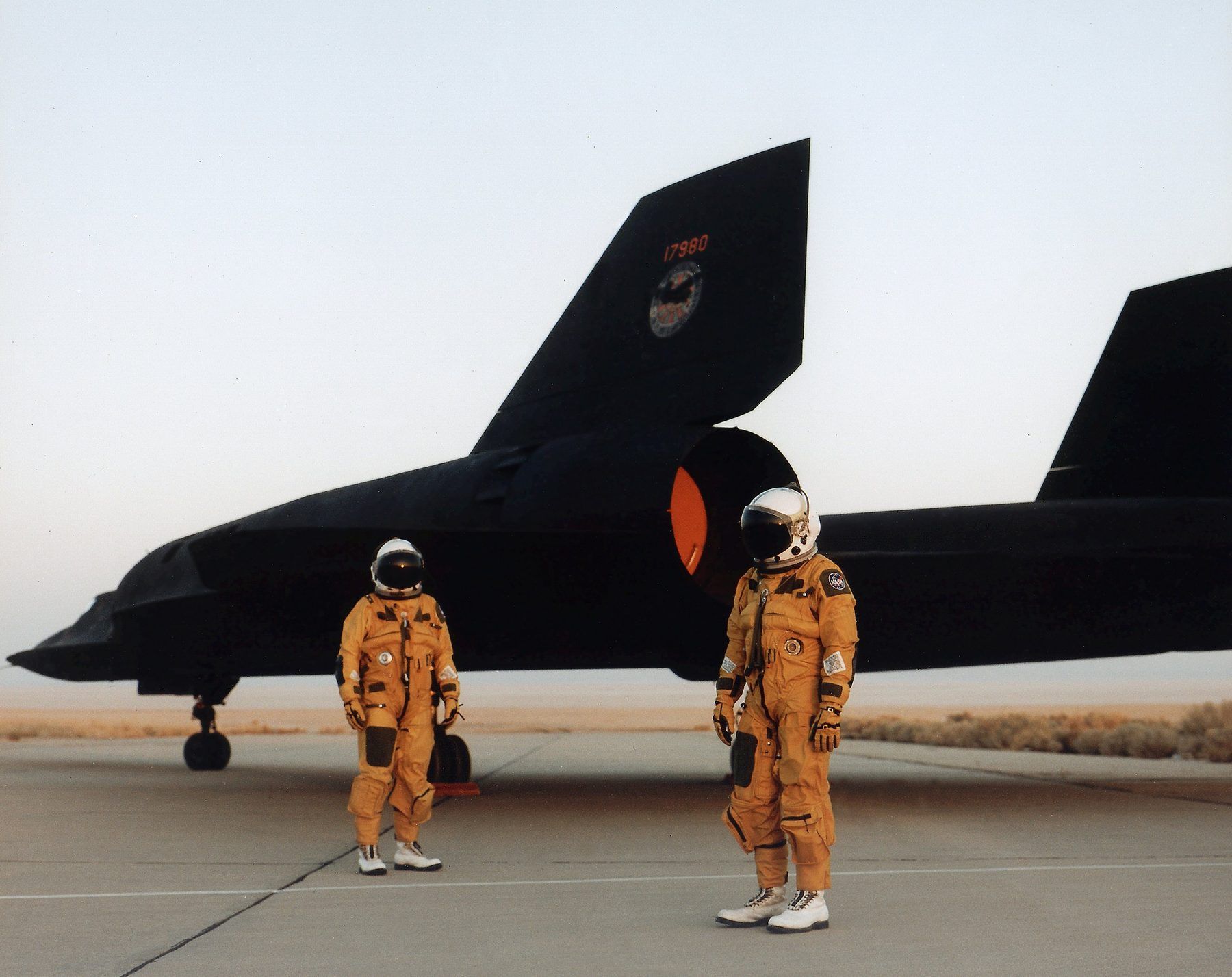
From late 1978 until 1996 they flew in David Clark S1030 full-pressure suits: six layers that hold 3.5 psi if the cockpit loses pressure.12,1

Sources on this page12
- U.S. Air Force. SR-71A-1 Flight Manual (T.O. SR-71A-1), Issue E, Change 2, 31 July 1989. Cited at p.5-8, p.5-10; p.1-4; Figure 1-32, p.1-48; p.1-4, p.1-7; p.5-8; p.5-10; p.1-31, p.1-43; p.1-31 to 1-35, p.1-42A; p.1-7; p.1-4 to 1-7; p.1-21; p.1-9, p.1-22; Figure 1-12, p.1-23; p.1-43; p.1-135 to 1-136; Figures 1-17 and 1-19, p.1-28 to 1-30; p.4-105; p.4-3 to 4-6, Figure 4-2; Figure 1-32, p.1-48; p.1-58 to 1-60; p.1-58, p.5-8; p.1-60; p.1-199 to 1-203; p.1-197; Figure 1-21, p.1-33; p.1-31, p.1-43; p.1-43; Figure 1-12, p.1-23; p.1-17; p.1-9; p.1-14, p.2-50; p.1-19; p.1-11; Figure 1-12, p.1-23; p.1-42A. Open · In the register
- NASA Technical Reports Server. Design and Development of the Blackbird: Challenges and Lessons Learned (Peter W. Merlin, AIAA 2009-1522). Cited at p.26; p.27; p.16; p.25; p.18. Open · Archived · In the register
- NASA Dryden Flight Research Center. NASA Facts FS-2008-6-030-DFRC: SR-71 Blackbird. Cited at p.3. Open · Archived · In the register
- NASA. YF-12 Propulsion Research Program and Results (Albers and Olinger, NASA CP-001, 1976). Cited at p.425. Open · Archived · In the register
- NASA History Division. Mach 3+: NASA/USAF YF-12 Flight Research, 1969-1979 (Peter W. Merlin, Monographs in Aerospace History No. 25, NASA SP-2001-4525). Cited at p.105; p.20, note 25; p.5. Open · Archived · In the register
- Central Intelligence Agency. A-12 Utility Flight Manual, changed 15 June 1968 (document C01316457). Cited at p.1-7. Open · Archived · In the register
- NASA. YF-12 Experiments Symposium, Volume 1 (NASA CP-2054, 1978). Cited at p.4. Open · In the register
- Central Intelligence Agency. Development of the Lockheed SR-71 Blackbird (Clarence L. Johnson, 1981), with J58/SR-71 Propulsion Integration (William R. Brown). Cited at Brown, p.2, Figure 1; Johnson, p.9; Johnson, p.10. Open · In the register
- Central Intelligence Agency, Center for the Study of Intelligence. Archangel: CIA's Supersonic A-12 Reconnaissance Aircraft (David Robarge, 2nd ed. 2012), p. 1. Cited at p.12; p.13. Open · Archived · In the register
- NASA. Mach 3 Legend: Design and Development of the Lockheed Blackbird (Peter W. Merlin, 2012). Cited at slide 33. Open · Archived · In the register
- U.S. Air Force. Deactivation of the SR-71 Program at Beale Air Force Base, California (environmental assessment, October 1990). Cited at p.1-4. Open · In the register
- NASA. Dressing for Altitude: U.S. Aviation Pressure Suits (Dennis R. Jenkins, NASA SP-2011-595). Cited at p.339 to 341. Open · Archived · In the register
Diagrams are pages of the declassified SR-71A-1 flight manual (1989) and NASA reports. Select one to read it at full resolution.